
Mining Rig Build Guide-19 GPU
STEP 3 / 組裝前框架 Composing front frame.
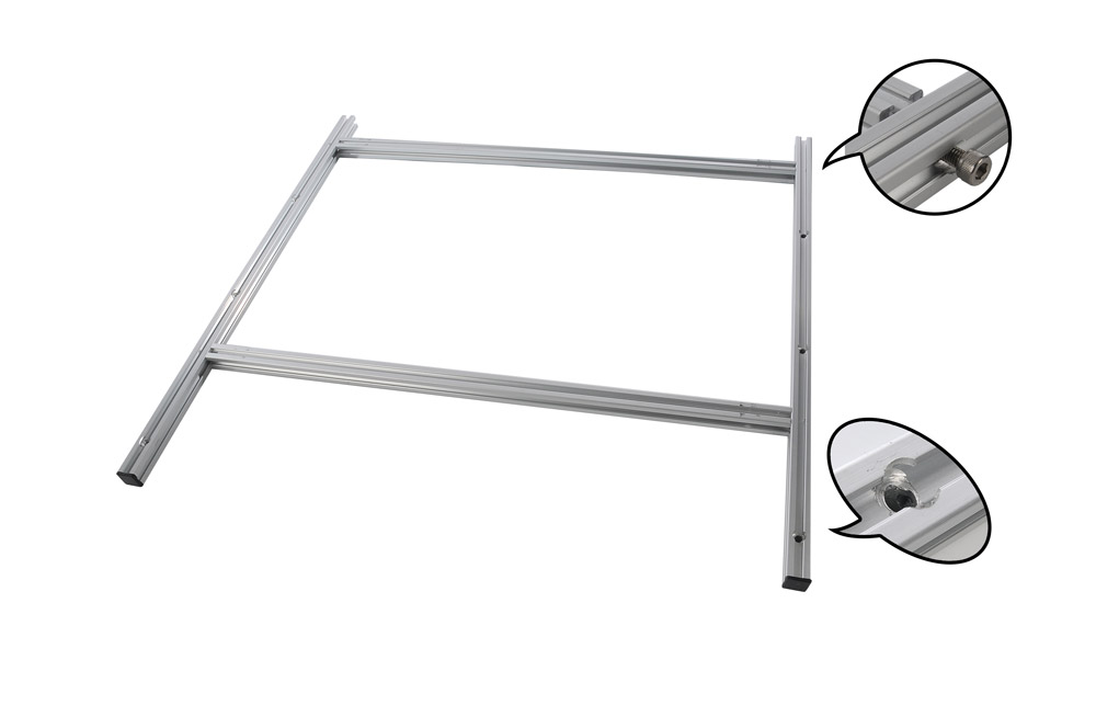
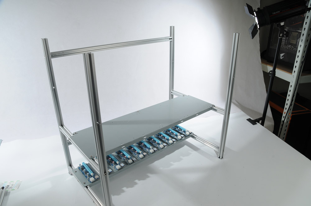
3.1 |使用4根M6螺絲(零件編號24)組裝 1組鋁擠條 60cm(L)(零件編號01)、1組鋁擠條 60cm(R)(零件編號02)、2組鋁擠條 60cm(零件編號04),請注意將鋁擠條 60cm(L)(零件編號01)、1組鋁擠條 60cm(R)(零件編號02)的沉頭螺絲孔朝外,完成以上步驟即完成前框架。
3.1 |Using M6 hexagon key to lock up one Aluminum Extrusion 60cm (L), a Aluminum Extrusion 60cm (R) and two Aluminum Extrusion 60cm with four M6 screws. Please make sure the countersunk holes on the Aluminum Extrusion 60cm (L) and Aluminum Extrusion 60cm (R) are facing out.
STEP 4 / 連接前框架、VGA鐵板 Composing front frame and VGA plate.
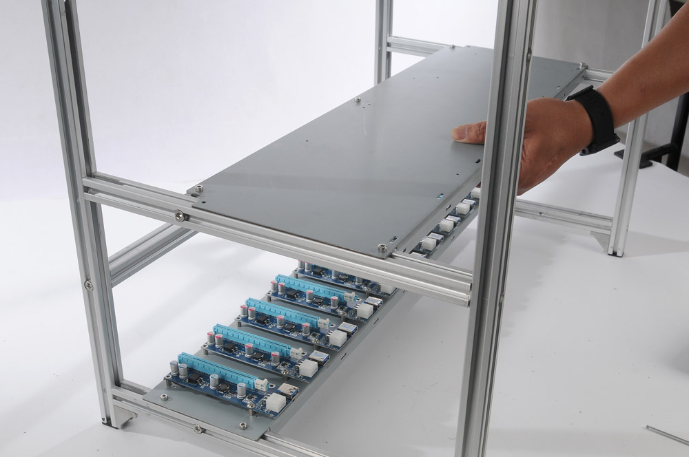
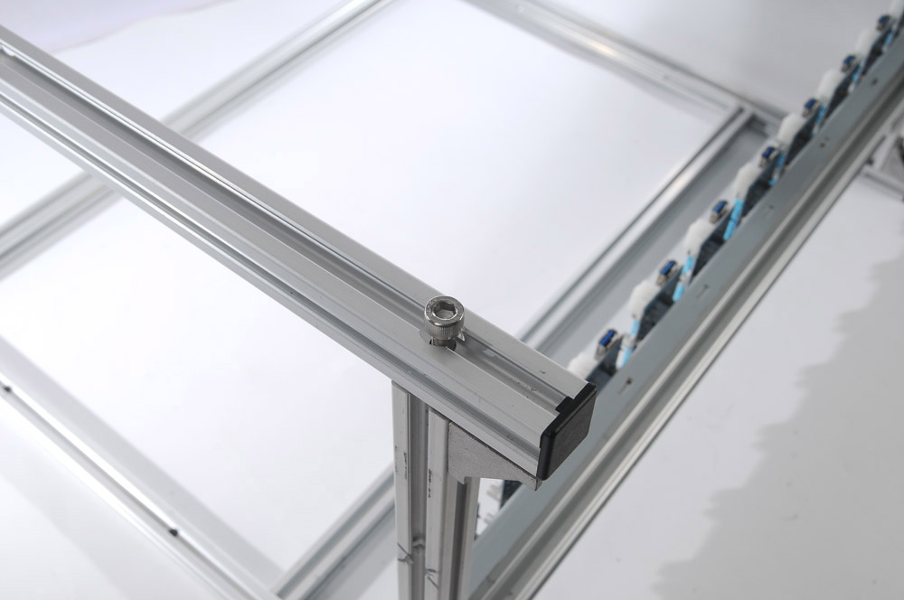
4.1|將 VGA底板從下往上安裝於前框架,使VGA鐵板的M4滑塊滑入軌道,並對準鎖孔,使用M6螺絲(零件編號24)鎖緊固定;取2組鋁擠條 60cm (back)(零件編號03),並利用VGA鐵板的M4滑塊定位。
4.1|Composing VGA plate and front frame from bottom up with two M6 screws, then use the two L shaped components which composed in STEP 1.5 to connect two Aluminum Extrusion 60cm. Use M4 hexagon key to locate and locking up the Aluminum Extrusion 60cm bar.
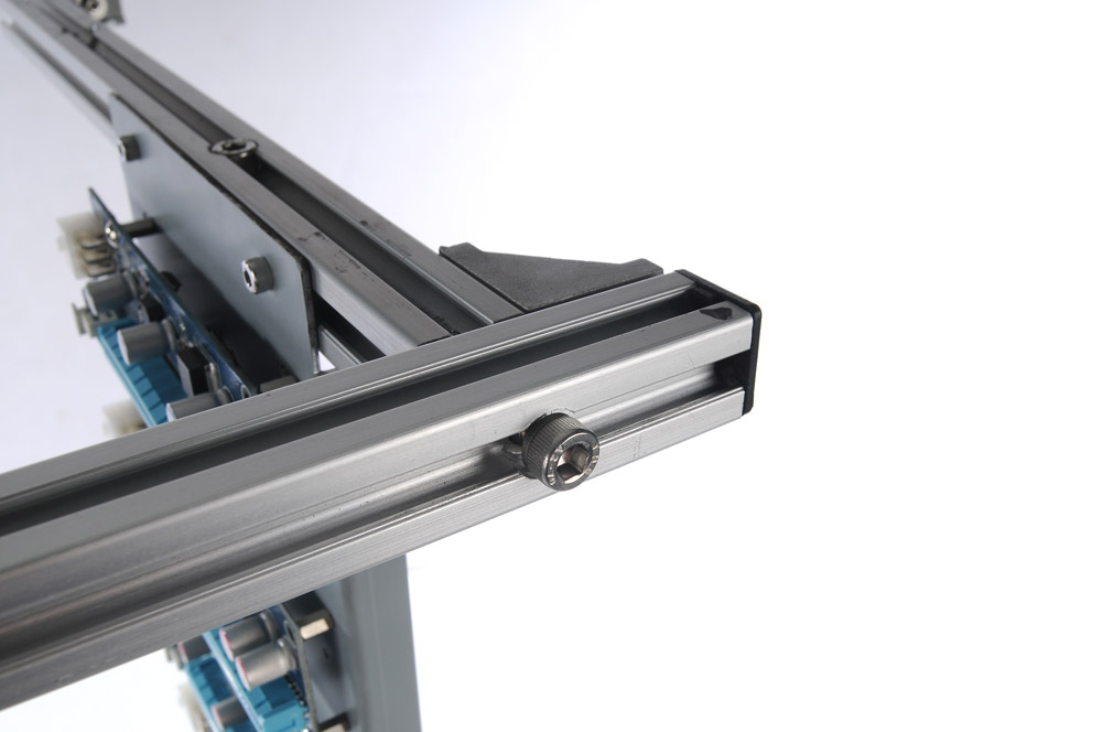
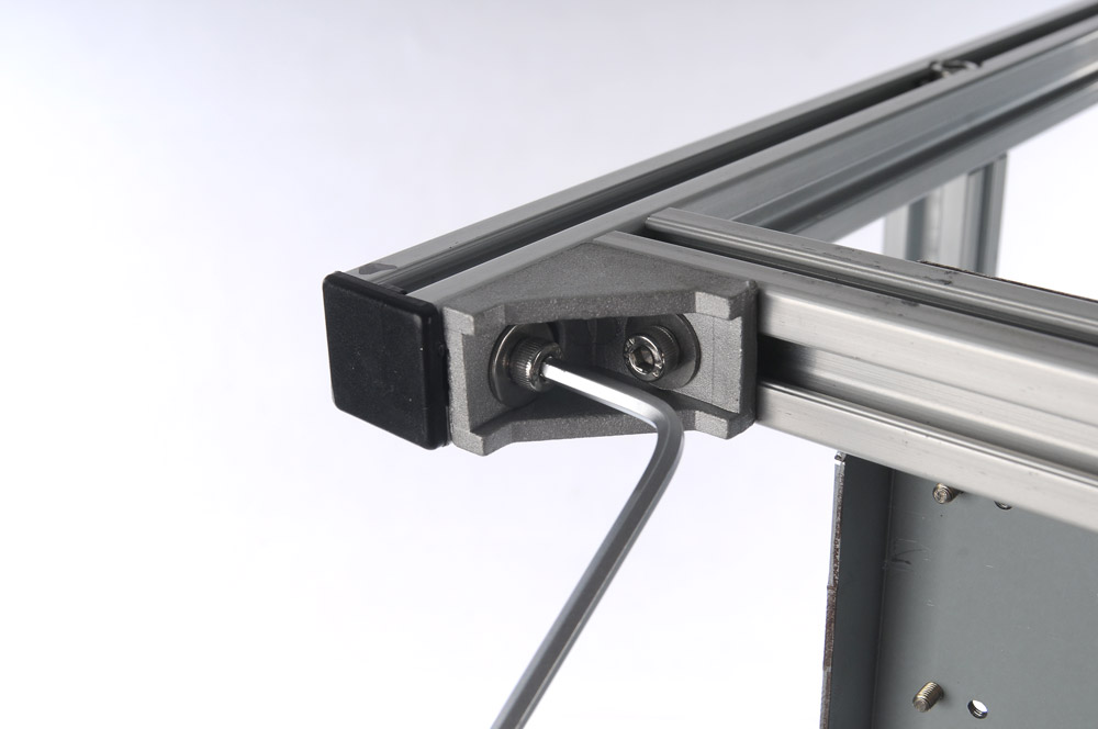
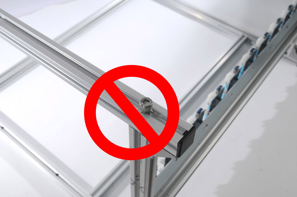
註:請勿先行安裝後端的M6螺絲(零件編號24),須等安裝完風扇組件後再行鎖緊固定。
Notice: Please do not lock M6 screw on the back side of mining rig until composing the lower fan assembly part, then user can install M6 screw to complete installation.
STEP 5 / 組裝 Mobo主機板底板 install Mobo plate.
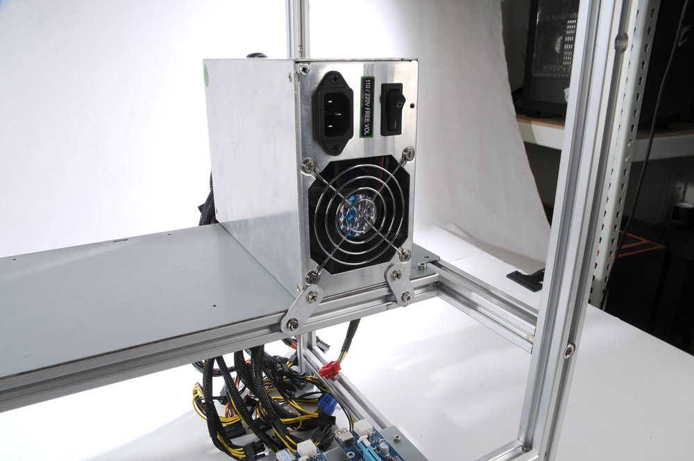
5.1 | 對準鎖孔並使用M6螺絲(零件編號24)鎖緊固定組裝 Mobo主板機底板,利用4組電源固定鐵片及電源螺絲(零件編號13)固定電源供應器,完成電源供應器定位即可鎖緊電源螺絲(零件編號13)及M4螺絲(零件編號10)。
5.1 | Using M6 hexagon key to install mobo plate with four M6 screws. Then use the four PSU connecting components to locate 2 PSUs. Tighten PSU screws and M4 screws of PSU connecting component.
STEP 6 / 組裝 上層VGA鐵架 install upper VGA plate
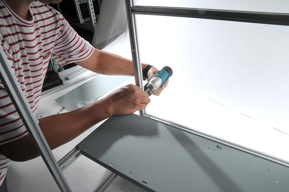
6.1 |對準鎖孔並使用M6螺絲(零件編號24)鎖緊固定組裝上層VGA鐵架。
6.1 |Using M6 hexagon key to install VGA plate with four M6 screws.
註:上層VGA鐵架無須安裝 L角固定組件。
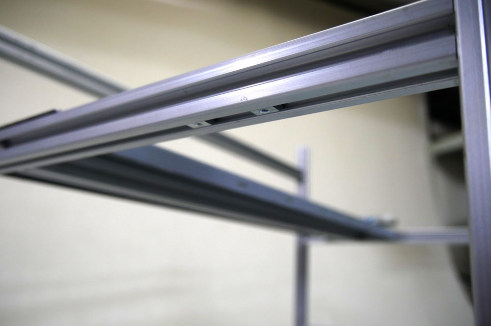
Optional: 2.5 inches SSD Installation
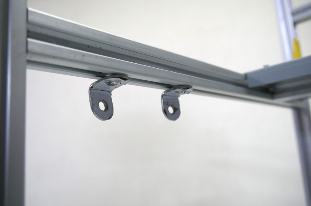
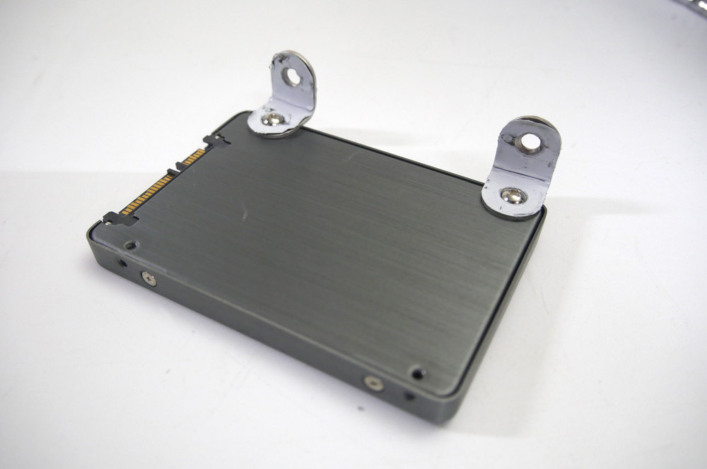
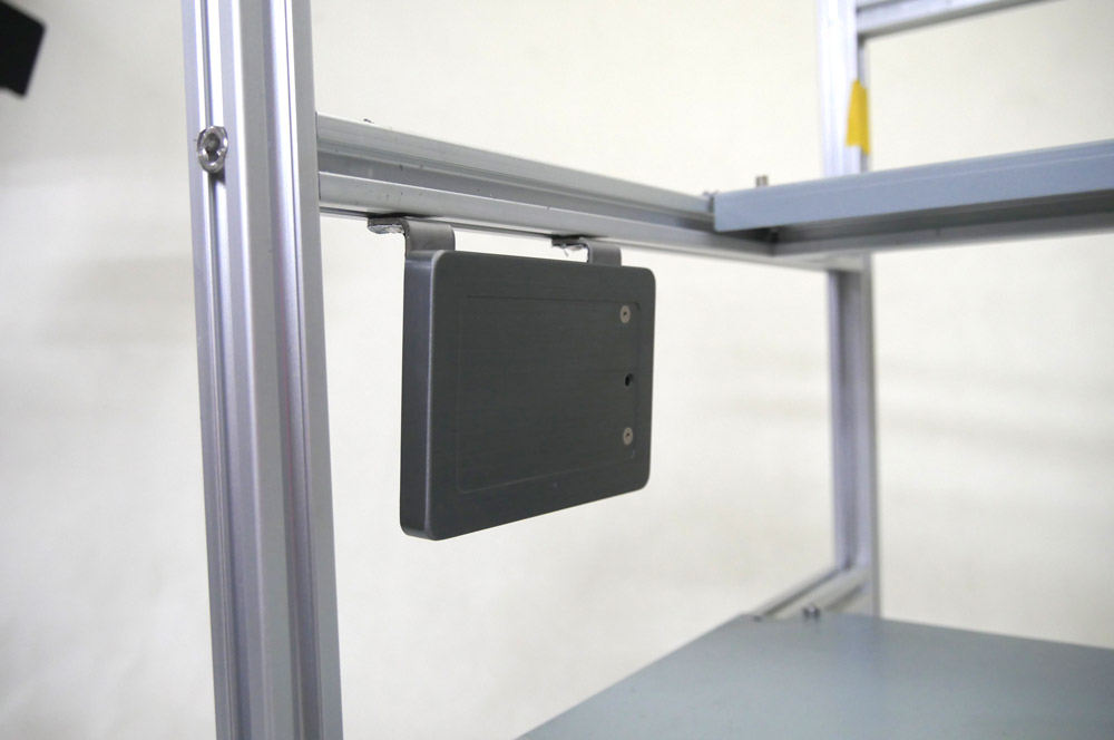
於鋁擠條35cm(零件編號05)之下方軌道放入2顆M3滑塊(零件編號14); 使用M3螺絲(零件編號09)組裝2.5吋SSD與SSD鐵片(零件編號16),請注意將SSD的接口處朝向礦架正面,再使用M3螺絲連結固定SSD於上層,再使用M3螺絲連結固定SSD於上層VGA鐵架的下方。
Before installing M6 Screw, put two M3 Insertion Nuts into bottom track of left side of Aluminum Extrusion 35cm of upper VGA plate.
Composing 2.5 inches SSD and SSD connector with two M3 screws.
Using two M3 screws to mount the SSD under upper VGA plate. Please notice the interface of SSD should face toward the front.
STEP 7
7.1|安裝顯示卡*19。
7.1|Installing 19 VGA cards.
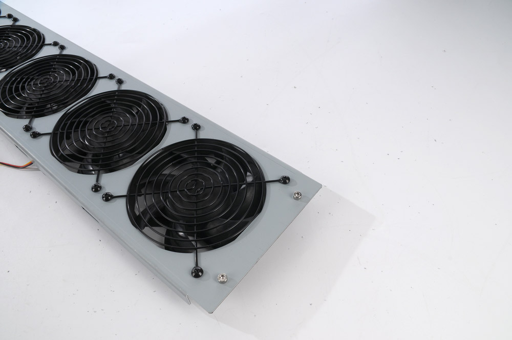
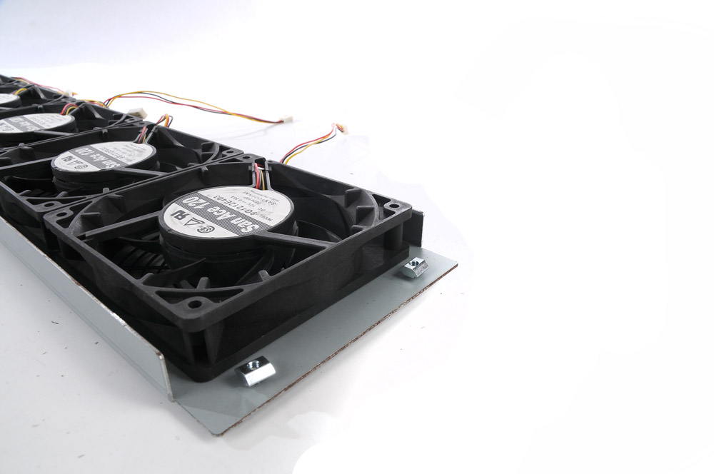
STEP 8 / 組裝風扇架,並安裝至礦架
8.1|於風扇架(零件編號07)上,使用內六角螺絲(短)(零件編號10)以及M4滑塊(零件編號15)組裝出鋁擠條固定點,共4組。
8.1|Use two M4 Hexagon screw A and two M4 insertion nut to compose two fixed point on both side of one Fan assembly.
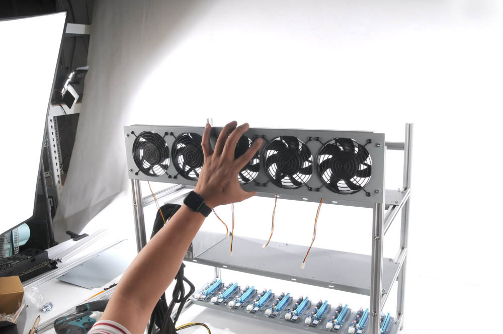
8.2|安裝風扇架*2,上端風扇架由上往下安裝,下端風扇架由下往上安裝。
8.2|Installing two Fan assemblies. The upper one should be installed from above, and the lower one should be installed from bottom up.
After locating proper height of Fan assembly, using M4 hexagon key to tighten the M4 Hexagon screw A to finish Fan assemblies installation.
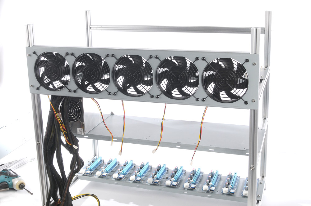
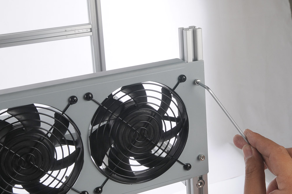
8.3|使用M6內六角螺絲扳手將底部VGA鐵板的M6螺絲鎖上固定,以完成礦架安裝。
8.3|Use M6 hexagon key to lock lower VGA plate with two M6 screws.
-
 堅持幫玩家撐起一片天!酷!PC【浮空島】【觀星台】【飛行石】正式登場。on 2026-07-23
 -
 這個暑假有「聲」有色!買微星 Infinite S3 系列電競主機,限量送電競耳機!on 2026-07-23
 -
 【即刻搶購】讓信仰具象化!ROG GM1000全息投影電競主機限量5台開搶!on 2026-07-23
 -


